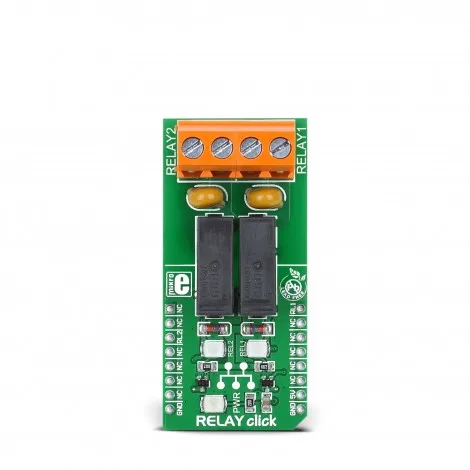
Relay click is a dual relay Click board, which can be operated by the host MCU. This Click board™ offers an elegant and easy solution for controlling a wide range of high power applications. Since it is able to operate on mains voltage level, it can even be used control the power for a number of small home appliances. It can also be used to activate various electromotors, switch on the lights, or power on the entire embedded system.
How does it work?
Relay click features two mini-relays, from Omron. Omron micro switches and relays are well known among enthusiasts and professionals alike, for their reliability and durability. Despite its size, the G6D-1A-ASI DC5 relay is able to withstand up to 5A and 220V AC/30V DC. It can endure up to 300,000 operations, with 30V DC and 2A. This relay has a single pole only - when the coil is energized, it will attract the internal switching elements and close the circuit, similarly to a switch.
These relays are designed so that their coils can be easily activated by relatively low currents and voltages. For the G6D-1A-ASI DC5 relay operated at 5V, the coil current is 40mA. This makes them a perfect choice for activating them by an MCU. However, some additional components have to be included for a proper operation:
A small NPN RET (Resistor Equipped Transistor) is used to provide enough current for the relay coil. Two resistors are already integrated into the RET, providing it with the correct biasing, so using RETs simplify the design. Since the MCU drives the relay coils through these RETs, their bases are routed to CS and PWM pins of the mikroBUS™.
There is a LED (in a different color for each relay) which signalizes the state of the relay. When the current flows through the RET, the coil will be energized, and the relay will be in the closed switch state. This current also flows through this LED, which will indicate that the relay switch is closed.
The Schottky diode is connected across the relay coil, preventing the NPN RET to become inversely polarized by the inert nature of the coil.
Two varistors are used to prevent voltage peaks when the load is connected or disconnected, protecting the relay contacts that way.
DO NOT TOUCH THE BOARD WHILE THE EXTERNAL POWER SUPPLY IS ON!
Note: RELAY click has exposed pins/pads. To stay safe take precaution when applying high voltage to the click. The click is to be used by trained personnel only when applying high voltage.
Specifications
Type
Relay
Applications
Board can be used for turning on/off lights, motors and other high power consumers within the maximum supported voltage/current levels
On-board modules
G6D1AASI-5DC power PCB relay
Key Features
Control up to 5A, 250V AC/30V DC loads. Screw terminals allow secure connection of the load. Reliable OMRON relays, protected with varistors from voltage spikes.
Interface
GPIO
Compatibility
mikroBUS
Click board size
L (57.15 x 25.4 mm)
Input Voltage
5V
Pinout diagram
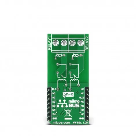
This table shows how the pinout of Relay click corresponds to the pinout of the mikroBUS™ socket (the latter shown in the two middle columns).
| Notes | Pin | Pin | Notes | ||||
|---|---|---|---|---|---|---|---|
| NC | 1 | AN | PWM | 16 | PWM | RL1 | |
| NC | 2 | RST | INT | 15 | NC | ||
| RL2 | CS | 3 | CS | RX | 14 | NC | |
| NC | 4 | SCK | TX | 13 | NC | ||
| NC | 5 | MISO | SCL | 12 | NC | ||
| NC | 6 | MOSI | SDA | 11 | NC | ||
| NC | 7 | 3.3V | 5V | 10 | 5V | Power supply | |
| Ground | GND | 8 | GND | GND | 9 | GND | Ground |
Relay click maximum ratings
| Description | Min | Typ | Max | Unit |
|---|---|---|---|---|
| Operational Current Range (30V DC / 250V AC) | 0 | - | 5 | A |
| Operational Voltage Range (AC) | 0 | - | 250 | V |
| Operational Voltage Range (DC) | 0 | - | 30 | V |
| Mechanical Endurance (2A, 30V DC) | 0 | - | 300,000 | operations |
Onboard settings and indicators
| Label | Name | Default | Description |
|---|---|---|---|
| LD1 | PWR LED | - | Power indication LED |
Software support
We provide a library for Relay click on our , as well as a demo application (example), developed using MikroElektronika . The demo can run on all the main MikroElektronika .
Library Description
The library offers an option to control the state of relays.
Key functions:
void relay_relay2Control( uint8_t pinState ) - Controls the Relay 2 pin.
void relay_relay1Control( uint8_t pinState ) - Controls the Relay 1 pin.
Examples Description:
The application is composed of three sections:
- System Initialization - Sets pin directions.
- Application Initialization - Initializes driver.
- Application Task - Turns relays on and off.
void applicationTask()
{
relay_relay2Control ( 1 );
relay_relay1Control( 1 );
mikrobus_logWrite("Relays turned on", _LOG_LINE);

Delay_ms(1000);

relay_relay2Control ( 0 );
relay_relay1Control( 0 );
mikrobus_logWrite("Relays turned off", _LOG_LINE);

Delay_ms(1000);
}
The full application code, and ready to use projects can be found on our .
Other mikroE Libraries used in the example:
- UART
Additional notes and information
Depending on the development board you are using, you may need , or to connect to your PC, for development systems with no UART to USB interface available on the board. The terminal available in all MikroElektronika , or any other terminal application of your choice, can be used to read the message.
mikroSDK
This click board is supported with - MikroElektronika Software Development Kit. To ensure proper operation of mikroSDK compliant click board demo applications, mikroSDK should be downloaded from the and installed for the compiler you are using.
For more information about mikroSDK, visit the .
Relay click projects
Relay click is featured in many Libstock projects with different platforms, here is a selection:

 Cart(
Cart(